
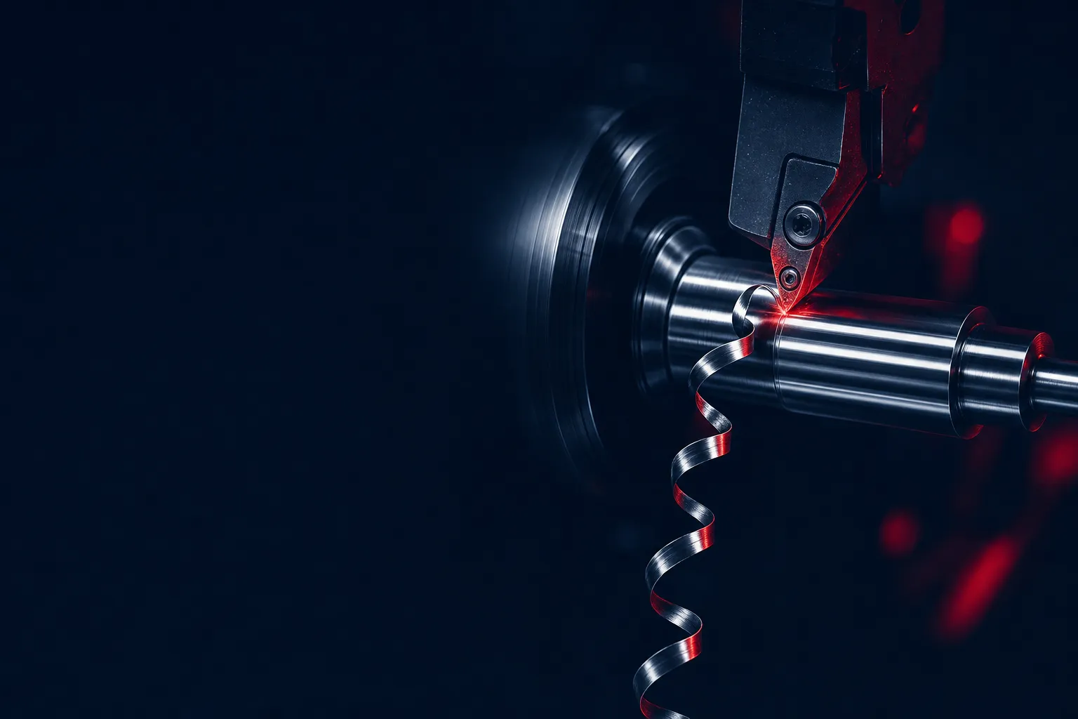
WORKPIECE ROTATESSINGLE-POINT TOOL FEEDS
TURNING
LATHE — THE PART SPINS
- ✓ Cylindrical geometry: shafts, bushings, fittings, threads
- ✓ Bar-fed production runs lights-out — lowest per-part cost
- ✓ On our floor: Mori Seiki NL2500SY · Doosan Puma turn-mills · bar to Ø3.2″
- ✓ Live tooling adds milled flats & cross-holes in the same setup
BEST TOL.
0.0002″
FINISH
16–63 µin Ra
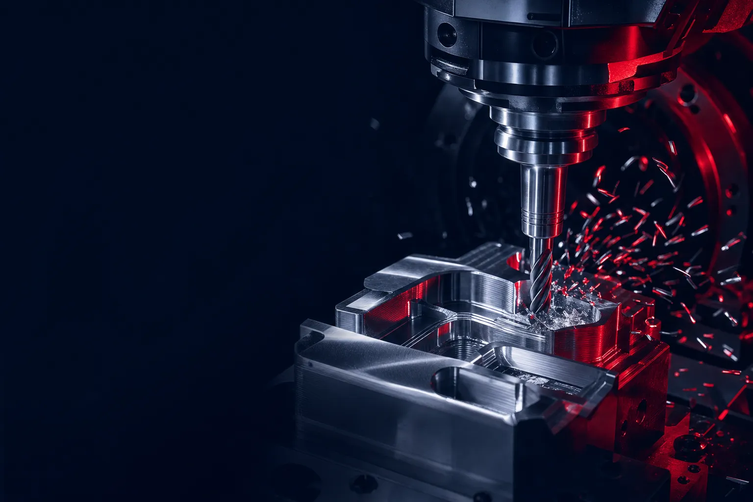
CUTTER ROTATESWORKPIECE FEEDS
MILLING
MACHINING CENTER — THE TOOL SPINS
- ✓ Prismatic & 3D geometry: housings, brackets, contoured surfaces
- ✓ Multi-point cutter — flats, slots, pockets, true 3D
- ✓ On our floor: Haas VF-6 (64″×32″×30″) · Kitamura Mytrunnion 4G 5-axis
- ✓ 5-axis holds the part once — kills tolerance stack-up between setups
BEST TOL.
0.0002″
FINISH
16–32 µin Ra
The math
we run
we run
RPM = 12·SFM / (π·D)
both processes — surface speed sets spindle speed
IPM = RPM·n·IPT
milling feed — n flutes × chip load
feed = IPR
turning feed — inches per revolution
| Feature | Turning | Milling |
|---|---|---|
| Main motion | Workpiece rotates | Cutter rotates |
| Cutting tool | Single-point | Multi-point (flutes) |
| Natural shapes | Cylindrical — Ø features | Prismatic & contoured |
| TPM machines | Mori Seiki · Doosan Puma · Tsugami Swiss | Haas VF-6 · Makino · Kitamura 5-axis |
| Best tolerance | 0.0002″ (0.0001″ Swiss) | 0.0002″ (5-axis) |
Rule of thumb: if the critical feature is a diameter, turn it. If it's a face, pocket, or contour, mill it. Round part with milled features? Our turn-mills do both in one setup.