



Engineering · GD&T
Position (true position).
The most-used GD&T tolerance for hole and feature locations. Position controls where a feature’s center, axis, or median plane must lie relative to a basic location specified by datums. Allows MMC modifier for bonus tolerance — making it more permissive than X/Y dimension tolerances while still controlling location.
01 · How to read the callout
Anatomy of the feature control frame.
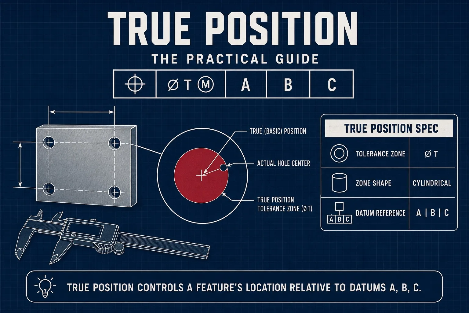
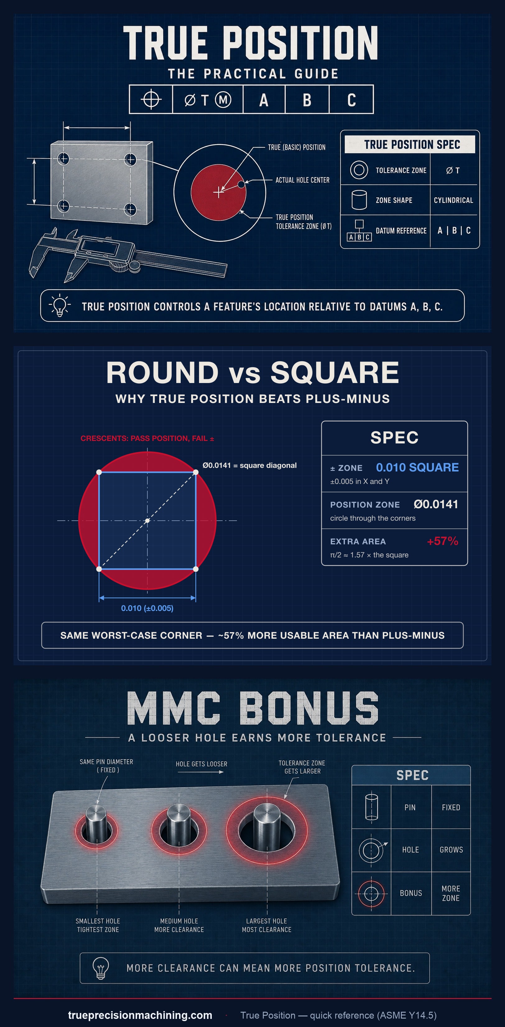
Every position callout reads as the same left-to-right sentence — this fully specified example has five parts: what is controlled, how big the zone is (and whether it grows), and from where it’s measured.
- Characteristic
Position — a location control. Needs basic dimensions and a datum reference frame.
- Zone + modifier
A Ø 0.005″ cylindrical zone (a diameter, not a radius). Ⓜ = tolerance applies at MMC, so bonus tolerance is earned as the hole departs from MMC.
- Primary datum
Seats the part — a planar primary like this one arrests 3 degrees of freedom. Inspection fixturing must match it.
- Secondary datum
Orients the part against the primary — arrests 2 more degrees of freedom.
- Tertiary datum
Locks the final degree of freedom so the basic dimensions have one fixed origin. Not every callout needs one — many patterns are fully constrained by two datums.
02 · Why position is the workhorse
Single tolerance, three benefits.
- Datum-based zones: the tolerance is referenced to a primary, secondary, and (sometimes) tertiary datum, so the inspection mounting matches the functional mounting
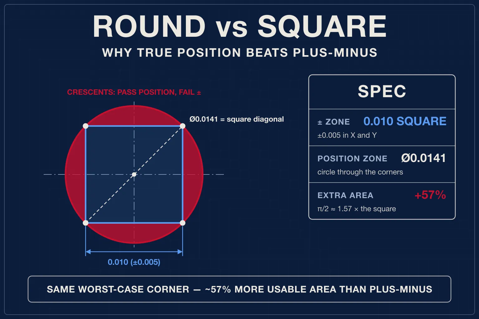
- Round beats square: the cylindrical zone holds ~57% more usable area than the ± coordinate square with the same worst-case corner — more good parts pass, same fastener clearance
- MMC modifier (bonus tolerance): as the toleranced feature departs from MMC, additional tolerance becomes available — and the callout becomes checkable with a fixed functional gauge
Converting a legacy print? ± coord × 2.83 ≈ position Ø — the full conversion table is on the true position calculator.
03 · Worked example
Bolt circle, MMC modifier.
A bolt pattern of six 0.250″ +0.005/−0.000 holes on a 4.000″ basic-dimension bolt circle, each called out as above. At MMC (Ø 0.250″) every hole axis must lie within a Ø 0.005″ cylinder at its basic location.
As a hole is drilled or reamed larger toward LMC, it earns bonus tolerance — bonus = actual size − MMC size — because a looser hole still clears the same fastener.
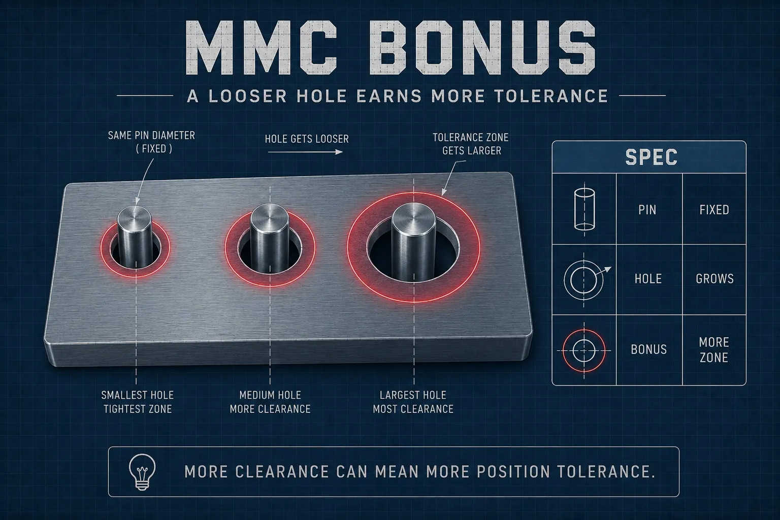
Bonus tolerance, by actual hole size
For this example: MMC Ø 0.2500″, position tol Ø 0.0050″ at Ⓜ.
| Actual hole Ø | Bonus | Total allowable Ø |
|---|---|---|
| 0.2500″MMC | +0.0000″ | Ø 0.0050″ |
| 0.2510″ | +0.0010″ | Ø 0.0060″ |
| 0.2525″ | +0.0025″ | Ø 0.0075″ |
| 0.2540″ | +0.0040″ | Ø 0.0090″ |
| 0.2550″LMC | +0.0050″ | Ø 0.0100″ |
04 · MMC vs RFS vs LMC
Three modifiers, very different behavior.
Tolerance applies regardless of feature size. The 0.005 zone stays 0.005 whether the hole is at MMC or LMC. Most restrictive — tightest control.
Use for: press fits, dowel locations, anywhere bonus would hurt function.
Tolerance applies at maximum material condition; bonus is earned as the feature departs from MMC. Most permissive — and checkable with a fixed functional gauge.
Use for: clearance-fit fastener patterns — the workhorse case.
Tolerance applies at least material condition; bonus is earned toward MMC. Protects minimum material.
Use for: wall thickness, hole-to-edge distance, cast bosses that must clean up.
05 · How it’s verified
CMM math, or a gauge that can’t argue.
Fixture on the datums in order (A, then B, then C), probe each hole to establish its actual axis, then compute the deviation from the basic location: position = 2 × √(Δx² + Δy²). Compare against the size-corrected allowable (tolerance + bonus at Ⓜ). The factor of 2 matters — the result is a diameter, compared against a diametral zone.
The MMC modifier makes the callout hard-gaugeable: a plate with pins at the virtual condition — for this example Ø 0.245″ (MMC 0.250 − 0.005 tol) — at each basic location. If the part seats on the gauge, the position callout passes; no math, no interpretation, and it checks size-and-location interaction exactly the way the mating part does. Hole size is still verified separately (a go/no-go plug gauge) — an oversize hole past LMC seats on the pins but fails the size limits.
Want to run your own numbers? The true position calculator does the axis math, MMC bonus, and pass/fail for up to 8 features in a pattern.
06 · Common mistakes
Where position callouts go wrong.
- Reading Ø 0.005 as ±0.005: the zone is a total diameter — the axis can be at most 0.0025″ from basic in any direction. A Ø 0.005 position callout is tighter than a ±0.005 coordinate callout, not equal to it.
- Comparing the radial deviation against the tolerance: the CMM’s r = √(Δx²+Δy²) must be doubled before comparing to the callout. Forgetting the 2× passes parts that should fail.
- Missing basic dimensions: position is measured from theoretically-exact (boxed) dimensions. If the locating dimensions carry ± tolerances, the callout is ambiguous.
- Expecting bonus without Ⓜ: RFS is the default per ASME Y14.5 — no modifier, no bonus, regardless of how the hole came out.
- Datum order that doesn’t match function: A|B|C determines fixturing sequence. If the part mounts on B in service but the print says A primary, inspection and function disagree.
Put it to work
Check a real pattern in seconds.
Enter basic and measured X/Y, hole size at MMC, and actual size — get actual position, MMC bonus, total allowable, and pass/fail per ASME Y14.5.
Keep exploring
Related tools & references
Full feature-control-frame symbol reference.
Convert X/Y deviation to a diametral position tolerance, with MMC bonus.
Check how positional tolerances accumulate in a pattern.
Legacy axis-location control superseded by position in most cases.
Removed from Y14.5-2018 (still seen on legacy drawings) — use position instead.
How tight a position callout drives cost.
Technically reviewed by the True Precision Machining engineering team · Last reviewed June 2026
Standards referenced: ASME Y14.5-2018
Have a part that needs to be made right?
Tell us about your part and we'll quote within 24 hours. Aerospace, medical, and defense work welcome.
Quotes in 24 hours