




Engineering · Reference
GD&T symbols — full reference.
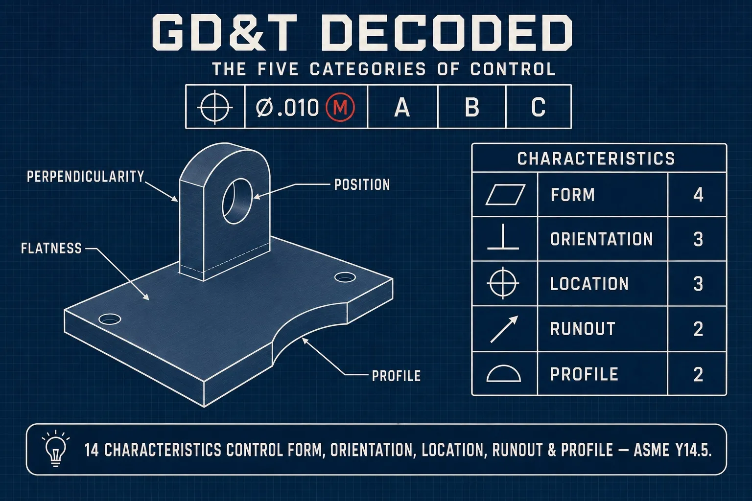
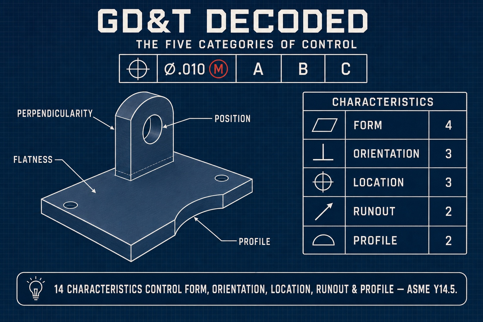
The 14 geometric tolerance characteristics in the GD&T system — the 12 current symbols in ASME Y14.5-2018, plus concentricity and symmetry (withdrawn in the 2018 revision but still found on legacy drawings) — organized by category (form, orientation, location, runout, profile). With plain-English definitions, datum requirements, and worked examples for each symbol.
Interactive Breakdown
GD&T Feature Control Frame (FCF)
Click any cell above to inspect the structural anatomy.
GD&T blueprints use a specialized rectangular compartmentalized block called a "Feature Control Frame" to guide high-precision inspection. This block defines the exact geometric criteria, boundaries, and alignment datums. Click on the cell components to learn their exact engineering roles.
Interactive Simulator
Tolerance Zone Simulator
Click a symbol to load its tolerance zone in the simulator.
Flatness Simulator
Drag the slider to vary the measured deviation — the verdict updates live.
Flatness Tolerance Zone: The spec face surface must completely lie between two parallel planes that are 0.010 in apart. Flatness does not reference any datums; it controls only the raw shape variation of the face.
Master Symbols List
| Symbol | Name | Category | Needs datum? | Definition | Example |
|---|---|---|---|---|---|
| — | Straightness → | Form | No | Surface line elements must lie between two parallel lines; when applied to an axis (derived median line, Ø in the frame), the axis must lie within a cylindrical zone. | Ø0.002 straightness on a shaft axis = the axis must lie within a 0.002-diameter cylinder. |
| ⏥ | Flatness → | Form | No | All points on a planar surface lie within a tolerance zone bounded by two parallel planes. | 0.001 flatness on a mounting face = the entire surface must fit between two parallel planes 0.001 apart. |
| ○ | Circularity (roundness) → | Form | No | At any cross-section, the surface must lie between two concentric circles separated by the tolerance value. | 0.0005 circularity on a bearing journal = no out-of-round at any single section. |
| ⌭ | Cylindricity → | Form | No | Combines straightness, circularity, and taper into one tolerance — the whole cylindrical surface lies between two coaxial cylinders. | 0.001 cylindricity = the surface meets straightness, roundness, and taper within 0.001 over the full length. |
| ∥ | Parallelism → | Orientation | Yes | A surface or axis must be parallel to a referenced datum within the tolerance zone. | 0.002 parallel to A = the surface must lie within two planes 0.002 apart parallel to datum A. |
| ⟂ | Perpendicularity → | Orientation | Yes | A surface or axis must be perpendicular to a referenced datum within the tolerance zone. | ⟂ Ø0.001 A = a hole axis must lie within a 0.001-diameter cylinder perpendicular to datum A (the Ø in the frame makes the zone cylindrical). |
| ∠ | Angularity → | Orientation | Yes | Surface or axis at a specific basic angle to a datum, within the tolerance zone. | 0.005 angularity at 30° to A = surface must lie in a zone offset 30° from datum A within 0.005. |
| ⌖ | Position (true position) → | Location | Yes | An axis or feature center must lie within a cylindrical or other-shape tolerance zone at the basic position relative to datums. | Ø0.005 ⌖ at A B C = hole axis must lie within a 0.005-diameter cylinder centered at the basic location. |
| ◎ | Concentricity → | Location | Yes | Median points of a feature lie within a cylindrical zone coaxial with a datum axis. Withdrawn in ASME Y14.5-2018 (still seen on legacy Y14.5-2009 drawings) — replace with position-of-axis or runout. | ◎ Ø0.001 A = all median points of the feature must lie within a 0.001-diameter cylinder coaxial with datum axis A. |
| ⌯ | Symmetry → | Location | Yes | Median points of feature lie within a planar zone symmetric to a datum plane. Withdrawn in ASME Y14.5-2018 (still seen on legacy Y14.5-2009 drawings) — replace with position. | 0.001 symmetry to A = all median points of the feature must lie between two parallel planes 0.001 apart, centered on datum plane A. |
| ↗ | Circular runout → | Runout | Yes | FIM (full indicator movement) at any single cross-section as the part rotates about a datum axis. | 0.002 circular runout to A = at any single section, a dial indicator reads no more than 0.002 as the part rotates about A. |
| ⌰ | Total runout → | Runout | Yes | FIM across the entire surface as the part rotates and the indicator traverses the surface — axially along a diameter, radially across a face perpendicular to the axis. | 0.003 total runout to A = the indicator stays within 0.003 across the full surface as part rotates. |
| ⌒ | Profile of a line → | Profile | Optional | A line element of a surface lies within a 2D tolerance zone defined by basic dimensions. Used for 2D profiles like a cross-section. | 0.005 profile of a line to A = at each cross-section, the line element fits within ±0.0025 of the basic shape. |
| ⌓ | Profile of a surface → | Profile | Optional | A 3D surface lies within a 3D tolerance zone defined by basic dimensions. Most commonly applied to complex curved or contoured surfaces. | 0.010 profile of a surface to A B C = the entire surface within ±0.005 of the basic shape, located by datums. |
Reading a feature control frame
Symbol → tolerance → modifiers → datums.
A feature control frame is read left to right: the geometric characteristic symbol, then the tolerance value (with shape modifier like Ø for cylindrical zone), then the material condition modifier (M = MMC, L = LMC, none = RFS), then the primary, secondary, and tertiary datum references.
- Ⓜ (MMC): tolerance applies at maximum material condition; bonus tolerance available as feature departs from MMC
- Ⓛ (LMC): tolerance applies at least material condition; uncommon
- RFS (regardless of feature size): default; tolerance applies at all sizes
- Ⓟ: projected tolerance zone (extends past the feature surface)
- Ⓕ: free state — tolerance applies in unrestrained condition
Practical guidance
Common GD&T mistakes.
- Concentricity and symmetry — avoid.
Both are difficult to verify and ambiguous in practice. Modern drawings replace concentricity with position-of-axis or total runout, and replace symmetry with position. Both were removed from ASME Y14.5-2018 (still seen on legacy drawings).
- Position (⌖) is your friend.
Single best GD&T tool for hole and feature locations. Allows MMC modifiers (bonus tolerance), datum-based zones, and is universally measurable on a CMM.
- Profile of a surface for free-form geometry.
For airfoil profiles, optical surfaces, conformal channels — profile-of-a-surface with datum references is the right control. Don’t try to dimension contoured surfaces with linear tolerances.
- Datum stack matters.
The choice of A/B/C datums determines how the part actually mounts during inspection. Pick datums that match the functional mounting surface — not the easiest face to indicate on a setup.
- For tolerance-cost trade-offs, see the ladder.
Tightening a position from 0.005 to 0.001 typically multiplies cost. See tolerance-cost ladder for the full curve.
Keep exploring
Related tools & references
The most-used control — deep dive on the position characteristic.
Controls form, orientation, and location of a feature at once.
Form control for planar datum faces.
Convert X/Y deviation to a diametral position tolerance with bonus.
How GD&T callouts map to achievable shop tolerances.
A clean title block and feature-control-frame layout to start from.
Technically reviewed by the True Precision Machining engineering team · Last reviewed June 2026
Standards referenced: ASME Y14.5-2018
Have a part that needs to be made right?
Tell us about your part and we'll quote within 24 hours. Aerospace, medical, and defense work welcome.
Quotes in 24 hours