




Engineering · Calculator
True position calculator.
Check planar position for hole patterns from basic and measured X/Y, MMC hole size, and actual size. Results cover position only, not full drawing acceptance: verify size limits, datum setup, axis orientation, and any composite requirements separately.
Pattern parameters
Hole-size limits and tolerance.
Features
Add holes in the pattern.
Up to 8 features. Basic X/Y is the CAD-defined location; measured X/Y is the CMM result; actual size is the inspected hole diameter.
Pattern result
Actual position = 2 × √((Δx)² + (Δy)²). With MMC modifier active, total allowable = position tolerance + (actual size − MMC size). RFS (no modifier) means actual size doesn't add bonus.
Visual CMM Target
Active: Hole #1Position Deviation Map
Theoretical CAD basic is at center (0,0). Solid ring is original tolerance zone. Dotted ring is expanded MMC zone. Click and drag the probe dot to visually inspect deviations.
Per-feature breakdown
Click row to select active feature| # | Δx (in) | Δy (in) | Actual position | Bonus | Total allowable | Margin | Result |
|---|---|---|---|---|---|---|---|
| Add features to see results. | |||||||
Understand it
What “true position” actually means.
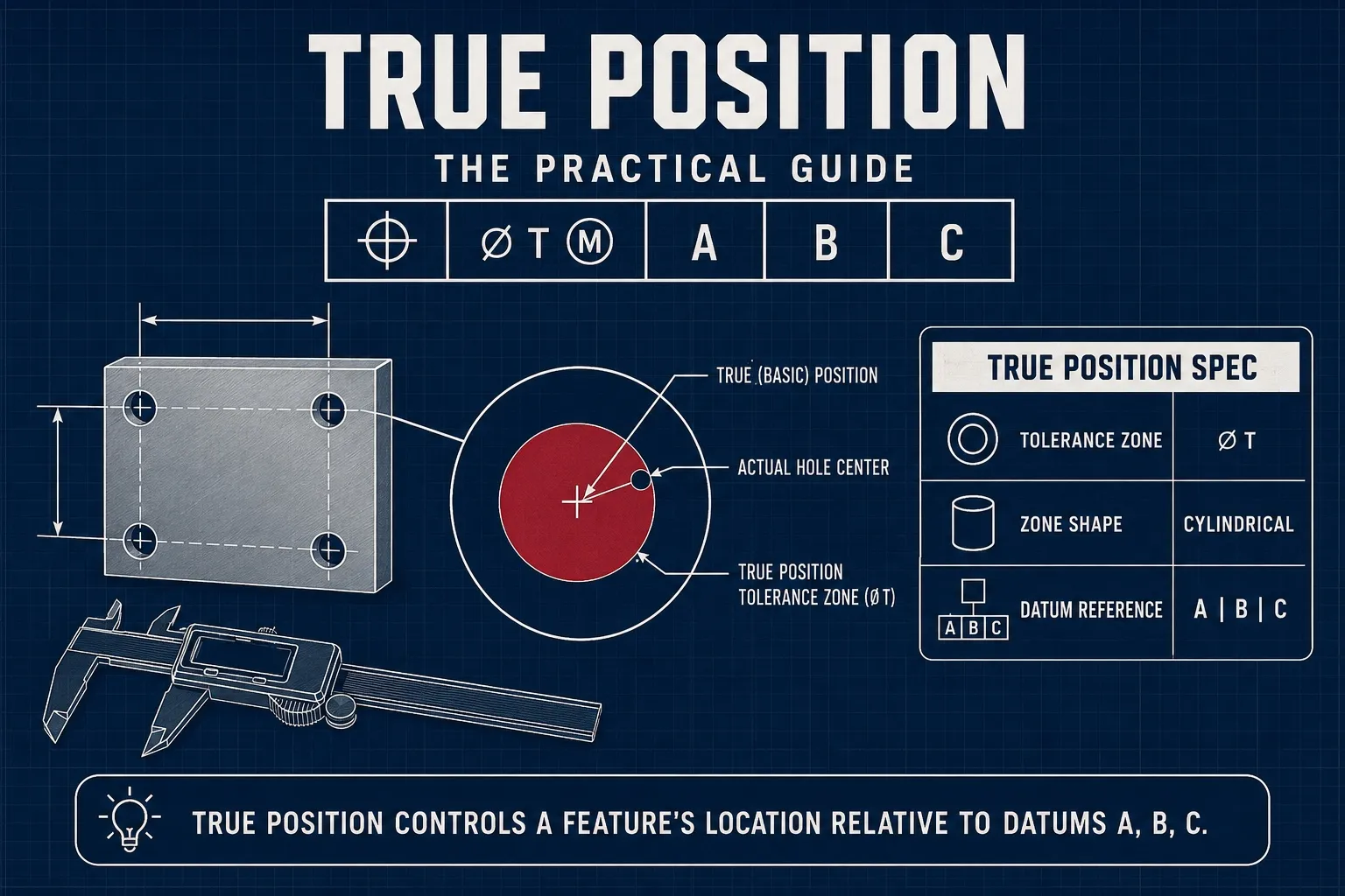
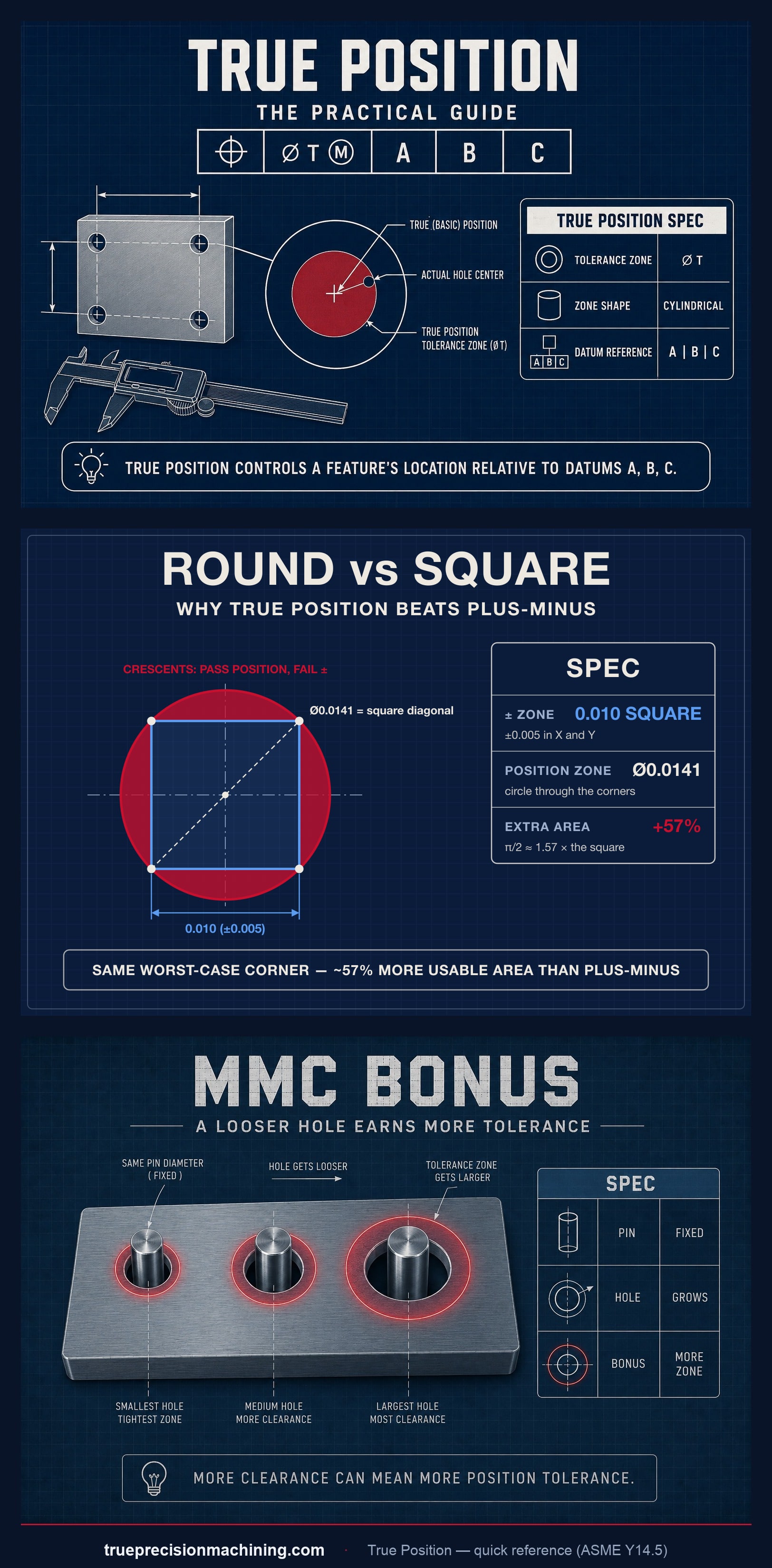
A position callout doesn’t give the hole a little box to live in — it gives it a round zone centered on the theoretically exact (basic) location. Here’s the picture, the formula, and the conversion machinists actually use.
Reference
Coordinate ↔ true position conversion
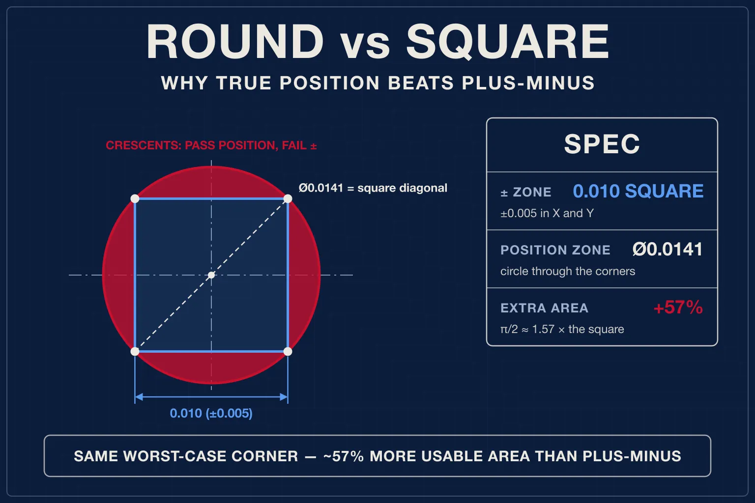
For equal ± X/Y tolerances, this circle encloses the square (diameter = 2√2 × coordinate tolerance). It also accepts points outside the square: these are not interchangeable drawing requirements.
| ± Coordinate tol | Enclosing circle Ø | Coord zone (□) |
|---|---|---|
| ± 0.0010″ | Ø 0.0028″ | 0.0020″ sq |
| ± 0.0020″ | Ø 0.0057″ | 0.0040″ sq |
| ± 0.0025″ | Ø 0.0071″ | 0.0050″ sq |
| ± 0.0050″ | Ø 0.0141″ | 0.0100″ sq |
| ± 0.0075″ | Ø 0.0212″ | 0.0150″ sq |
| ± 0.0100″ | Ø 0.0283″ | 0.0200″ sq |
| ± 0.0150″ | Ø 0.0424″ | 0.0300″ sq |
| ± 0.0200″ | Ø 0.0566″ | 0.0400″ sq |
Rules of thumb
- A round position zone gives 57% more tolerance area than the ± square that fits inside it — same worst-case corner, more room everywhere else.
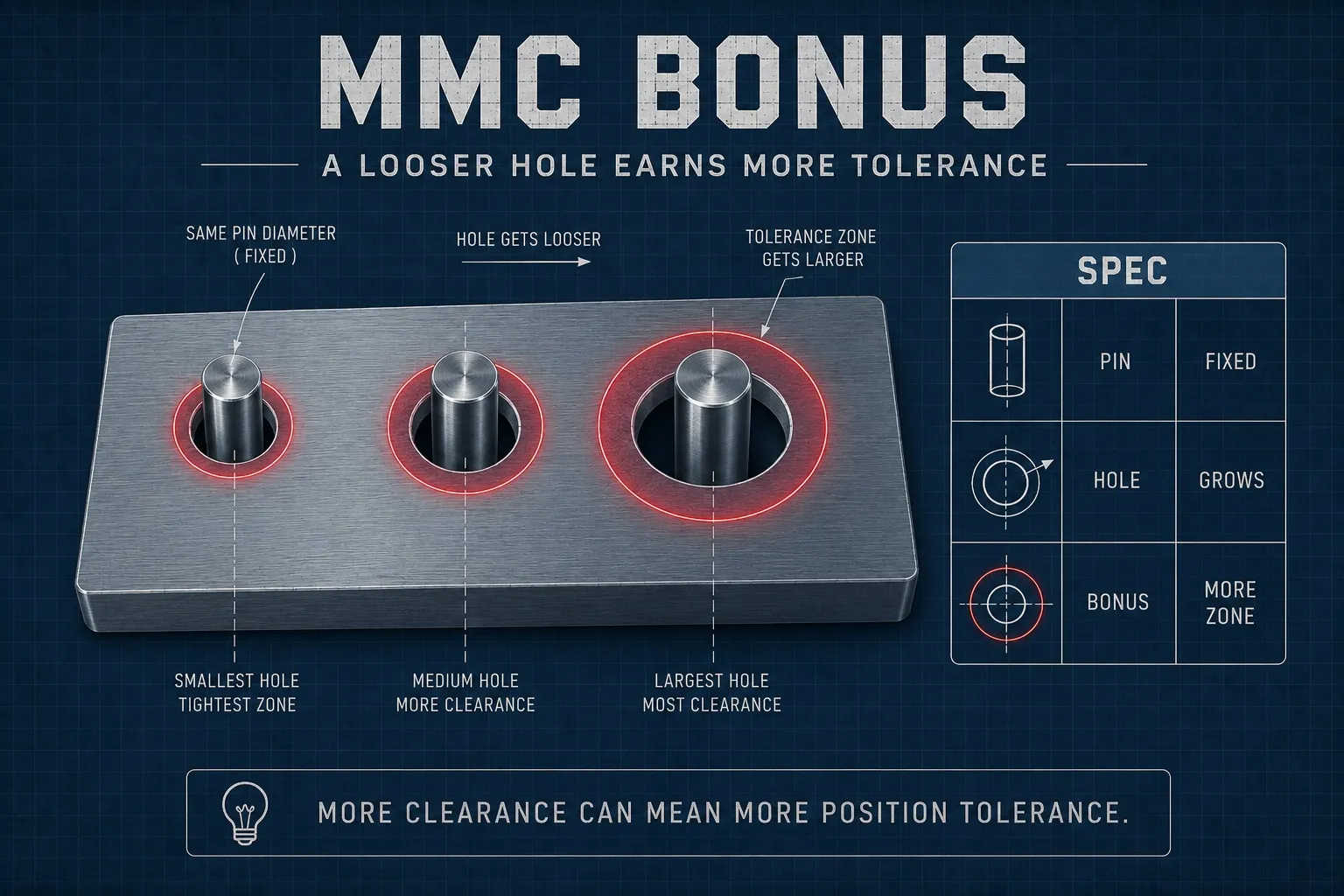
- MMC bonus = actual size − MMC size. A looser hole earns extra position tolerance because it still clears the fastener.
- Clearance-hole rule: position Ø ≈ hole Ø − fastener Ø (floating fastener — each part gets the full amount; fixed fasteners get (hole − fastener)/2 per part).
How it works
Position math, in plain English.
Actual position is a diameter, not a radius.
If your hole is 0.0015″ off in X and 0.002″ off in Y, the radial deviation is √(0.0015² + 0.002²) = 0.0025″. Position is 2× that = 0.0050″. The tolerance zone is a cylinder, so you compare against diameter.
MMC bonus = (actual size − MMC size).
If MMC is Ø 0.250″ and the hole came in at Ø 0.253″, you have 0.003″ of bonus. Total allowable position = original tolerance + bonus. The functional rationale: a bigger clearance hole tolerates more positional error.
RFS (no modifier) ignores actual size.
Default ASME behavior with no Ⓜ modifier: position tolerance is the position tolerance, regardless of how the size came out. Strictest.
Bonus only goes one way.
With MMC active, a hole below the entered MMC size is flagged BELOW MMC and cannot pass this check. Bonus is clamped at zero. An optional upper size limit can also flag oversize holes. Without it, upper size is not checked.
For the full GD&T background, see position (true position) reference.
Keep exploring
Related tools & references
The characteristic this calculator evaluates.
MMC, datums, and feature control frame basics.
Combine position with the rest of the dimensional stack.
Size limits that set MMC and bonus tolerance.
Hole-and-pin fits behind positional callouts.
Need true position held on a hole pattern?
Send your drawing and we'll confirm the positional tolerance we can hold and quote CMM inspection to match. Aerospace, medical, and defense work welcome.
Do not submit controlled technical data through public forms. Contact us first to arrange secure transfer of controlled drawings and requirements.
Quotes in 24 hours