



Engineering · DFM
Design for Manufacturing — the practical guide.
The geometry decisions that drive cost. Wall thickness minimums, hole ratios, corner radii, thread choices, and the tolerance traps to avoid before sending a drawing out for quote.
The 80/20 of part cost
Cost is locked in at design — not at the cutter.
By the time a drawing reaches the shop, somewhere between 70–90% of the part’s manufactured cost is already determined. Material choice, tolerance callouts, surface finish requirements, and basic geometry are the levers — and they’re all design decisions.
The good news: a 5-minute DFM review before quote routinely cuts 15–30% off finished cost without compromising what the part needs to do. The general patterns below apply to most parts. For process-specific guidance, see the dedicated CNC and EDM references.
ASME Y14.5m / ISO Compliant Standards
Standard DFM Tolerances & Clearances
Standardize your CAD geometries to match high-yield machining workflows. Design constraints aren't limits on creativity—they're the blueprints for manufacturing cost reduction.
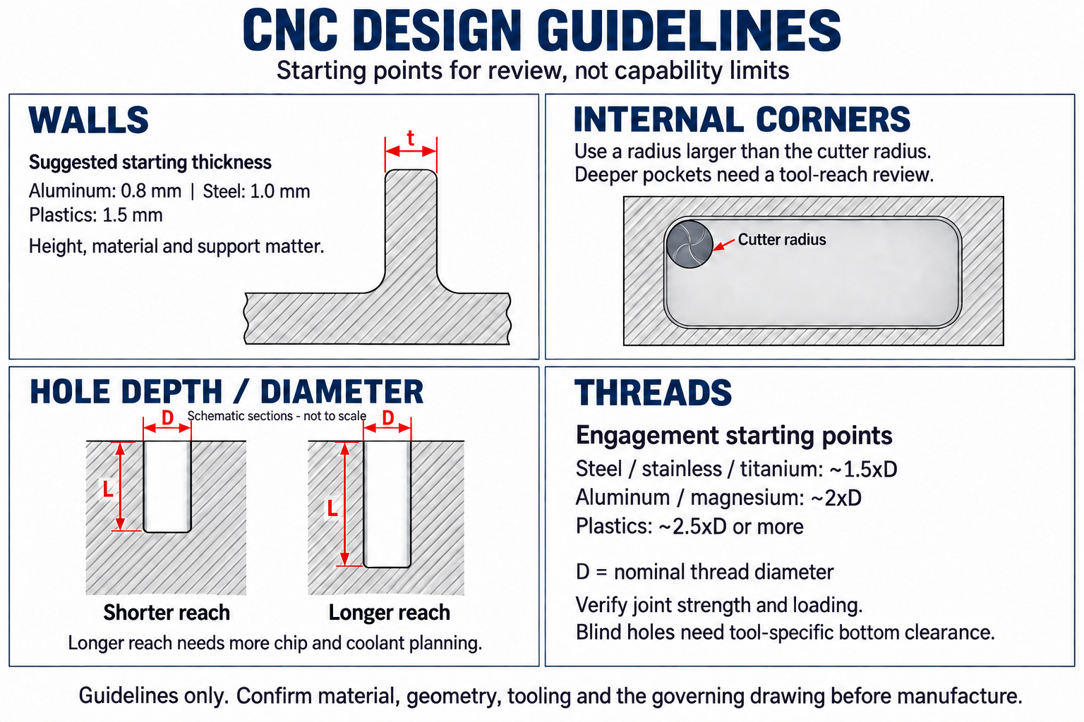
Wall Thickness Thresholds
Aluminum: ≥0.8mm (0.032") | Plastics: ≥1.5mm (0.060")
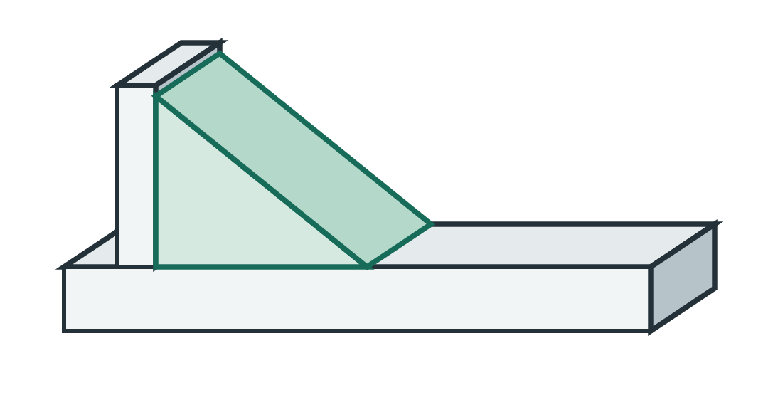
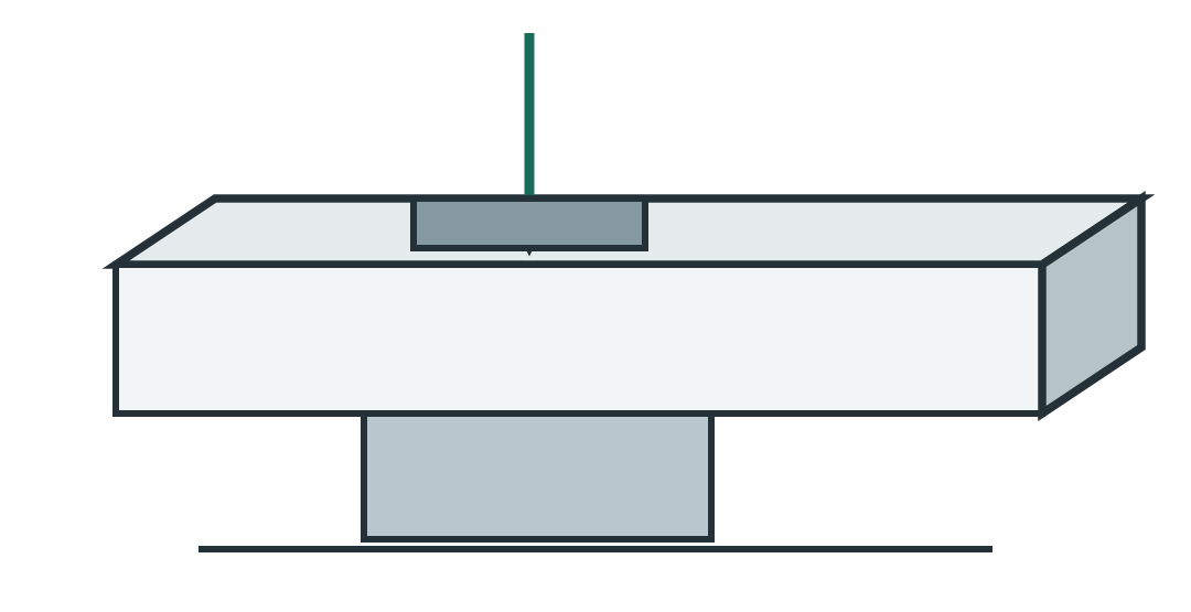
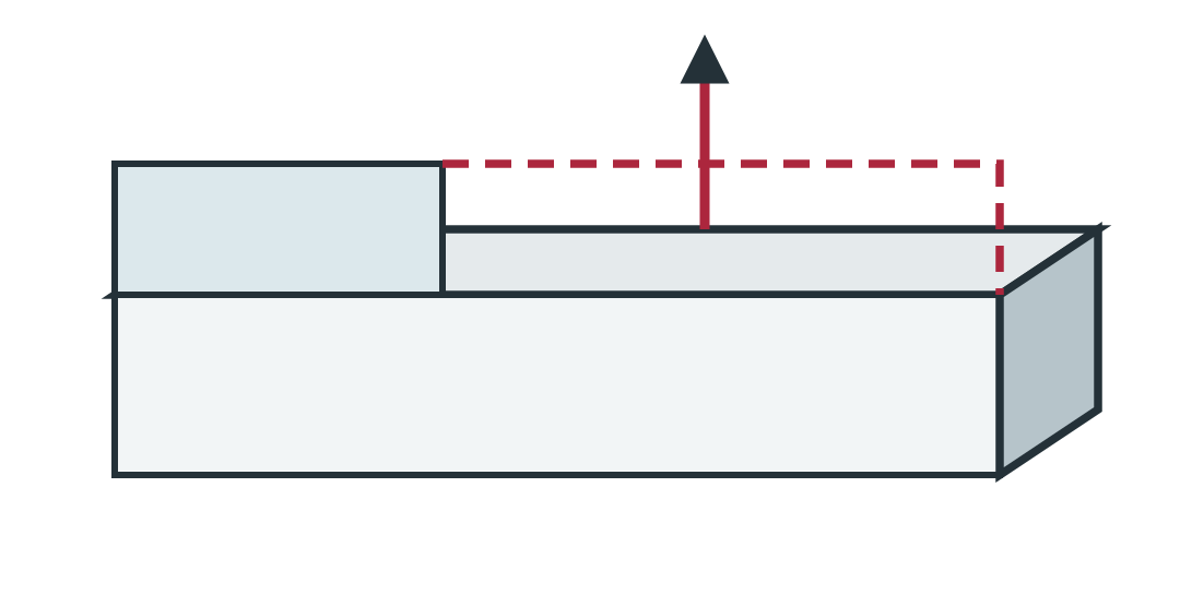
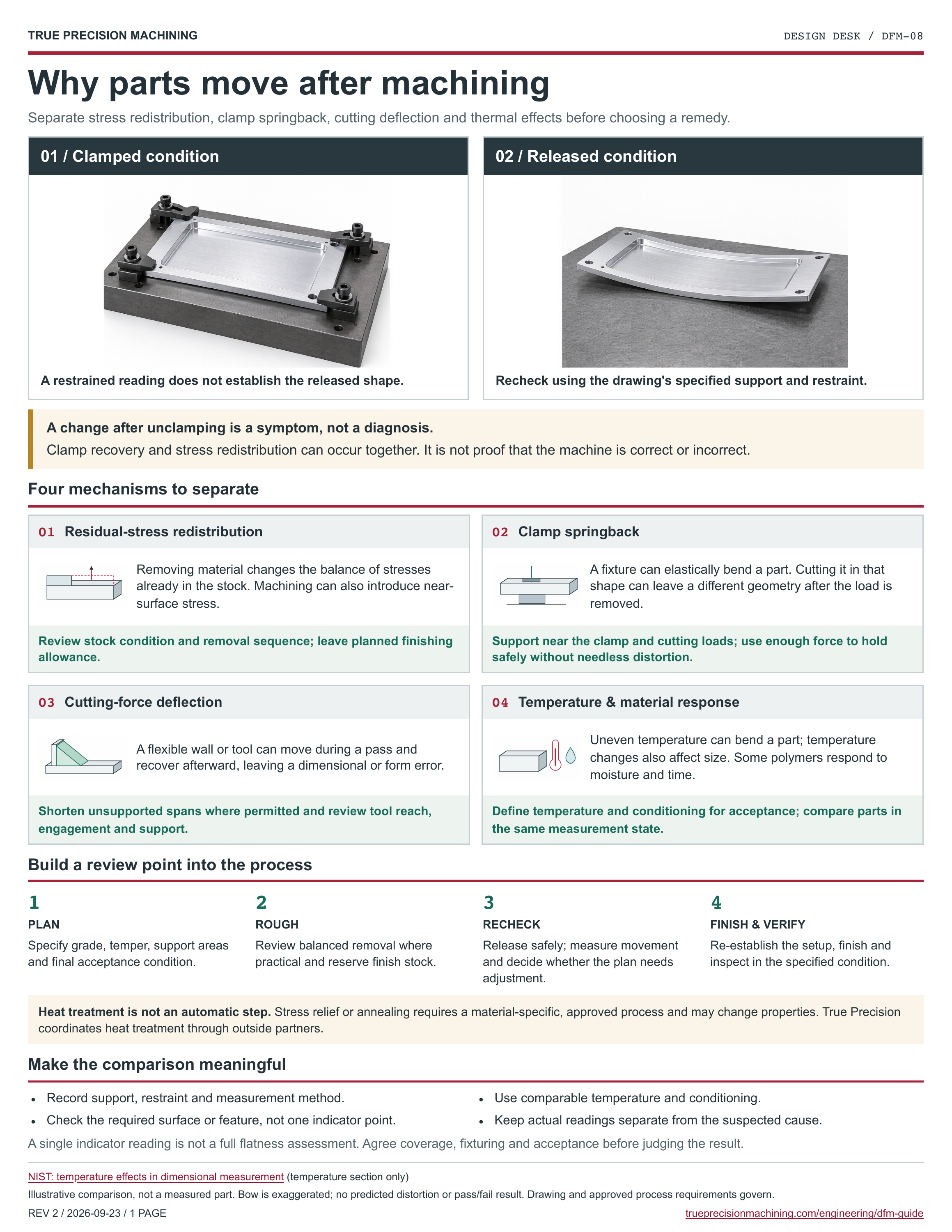
Thin walls flex under tool pressure, inducing chatter, dimensional drift, and geometric blowouts. Ensure robust ribbing and pocket-to-pocket offsets.
Pocket Depth Aspect Ratios
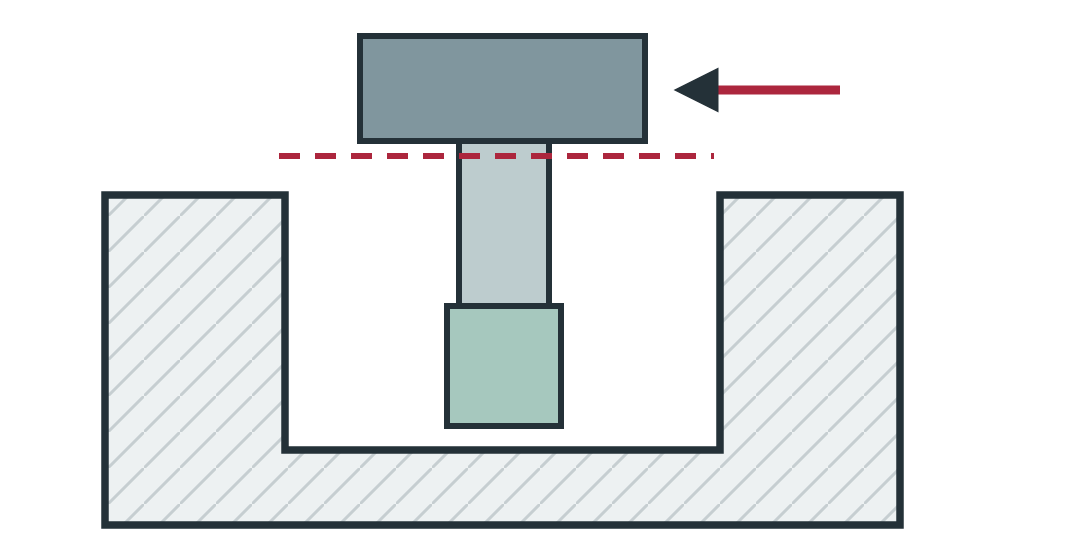
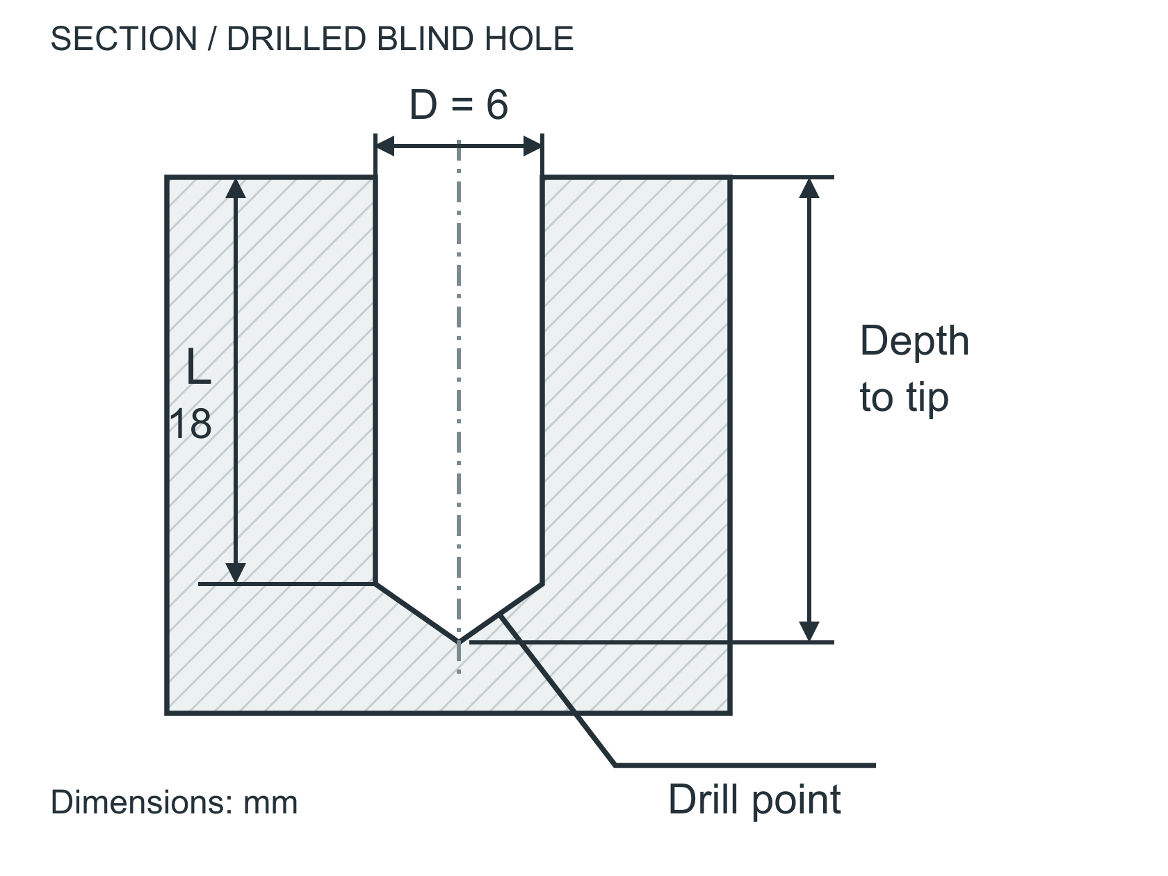
Standard: L:D ≤ 3:1 | Maximum CNC Limit: L:D ≤ 8:1
Deep pockets require long-reach endmills. Tool deflection increases exponentially with length-to-diameter ratio, reducing precision and slowing feed rates.
Internal Corner Sweep Ratios
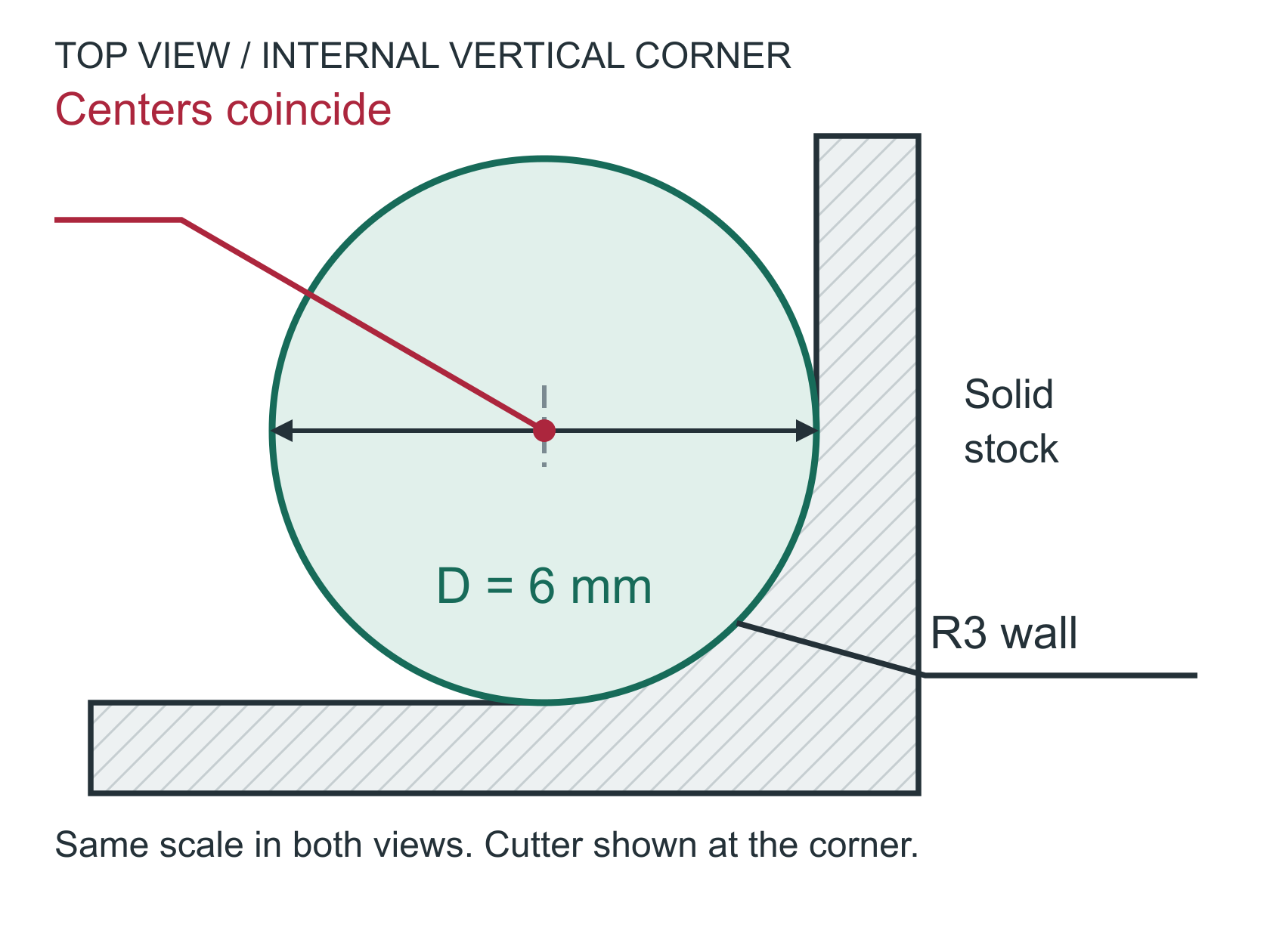
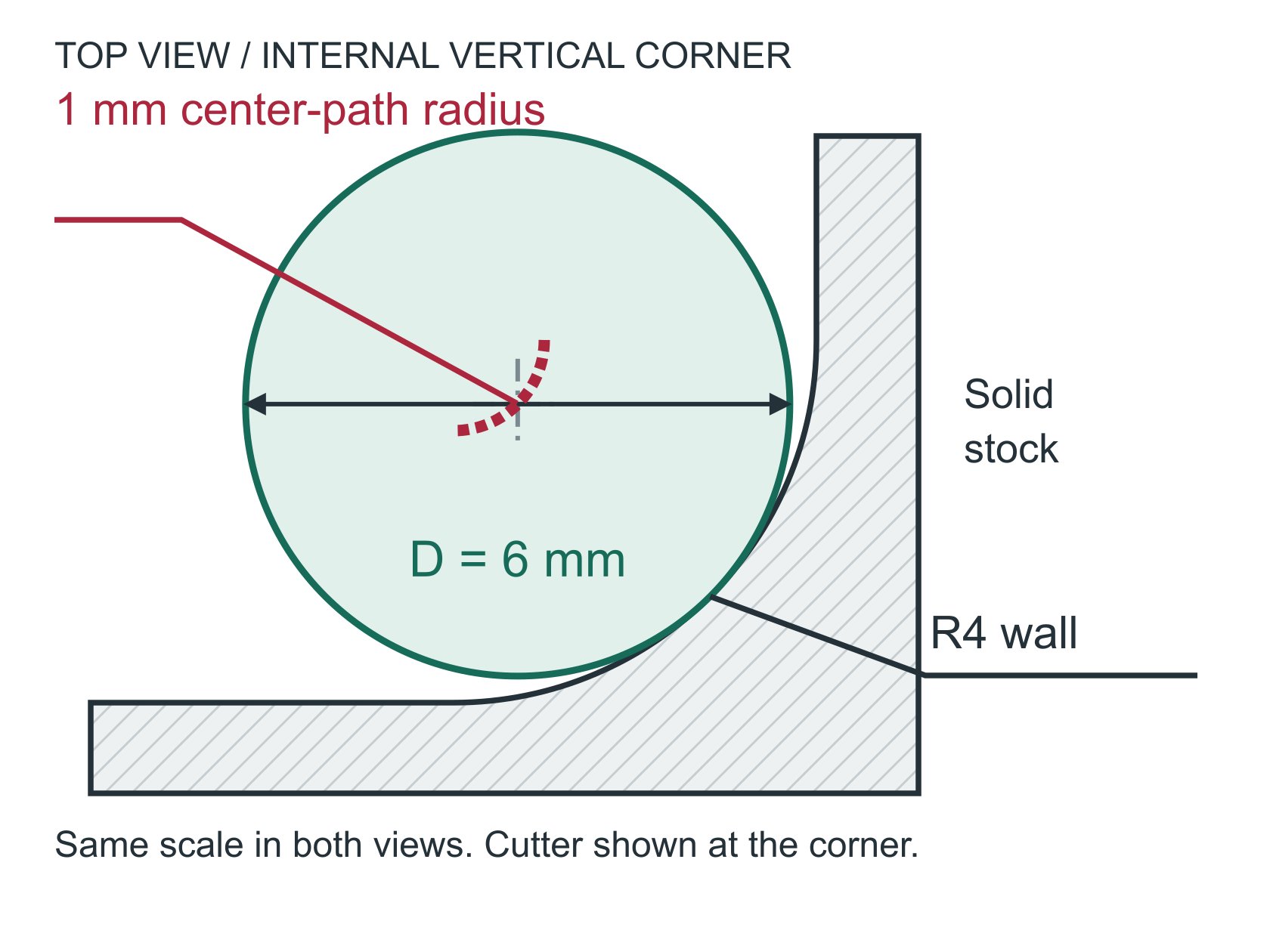
Fillet Radius: ≥1.3 × Endmill Radius (R > r_tool)
Never design sharp 90-degree internal pocket corners unless using EDM. Provide generous corner fillets so the endmill can sweep instead of digging in, eliminating chatter.
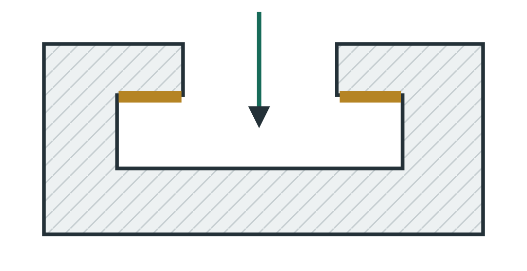
Thread Relief & Blind Hole Margins
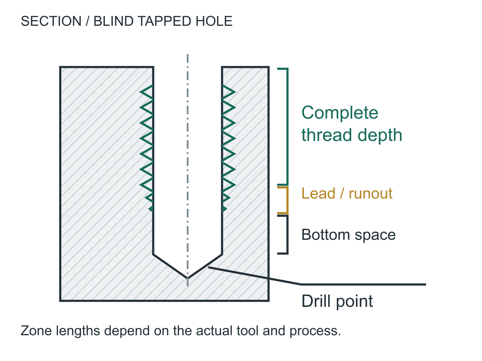
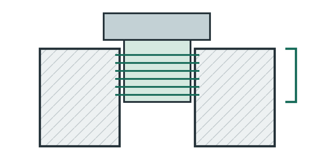
Extra Depth: ≥1× Thread Diameter beyond tap depth
Taps need lead-in chamfers and bottom clearance to flush chips out. Avoid threading to the absolute bottom of a blind hole to prevent tool breakage.
Process-specific best practices
CNC Milling & Turning
DFM for CNC machining →
Pocket geometry, tool reach limits, drill standards, threading, and the milling-specific design rules that drive cycle time and finish quality.
Wire EDM
DFM for Wire EDM →
What EDM can do that milling can’t — sharp internal corners, hardened materials, thin webs. Capability ranges, surface finish per pass, and when to choose EDM over milling.
Interactive Visualizer
Interactive DFM Cost Simulator
Toggle key geometric features to visualize real-time DFM checks and watch how simple design decisions stack up to drive standard manufacturing costs.
DFM Parameters
Manufacturing Multiplier
All parameters set to standard efficiency baselines.
This geometric layout is highly cost-effective. Wall thicknesses are rigid, internal pocket corners accommodate high-speed roughing cutters, hole aspect ratios are within twist-drill limits, and setup tolerances are standard as-machined specs.
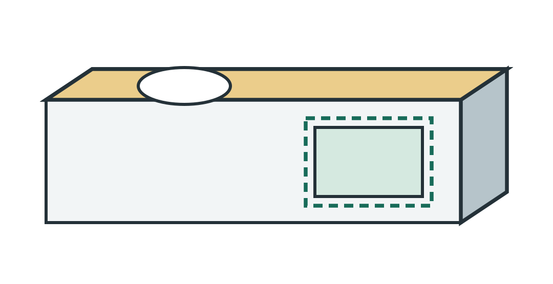
Key: red dashed = chatter risk · ✗ / ⚠ = DFM violation flag · red circle = endmill cutter
01 · Wall thickness
Mind the minimums.
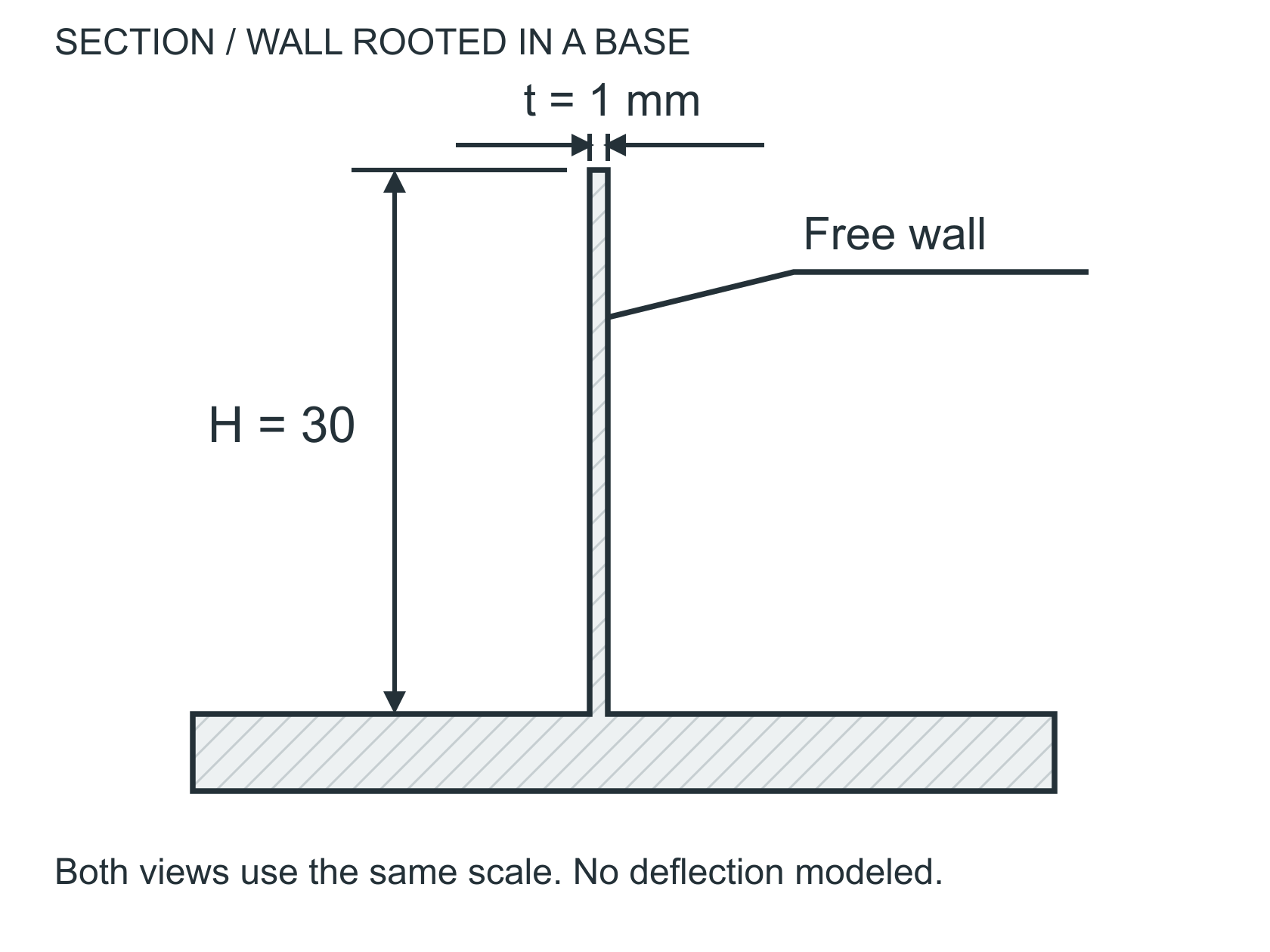
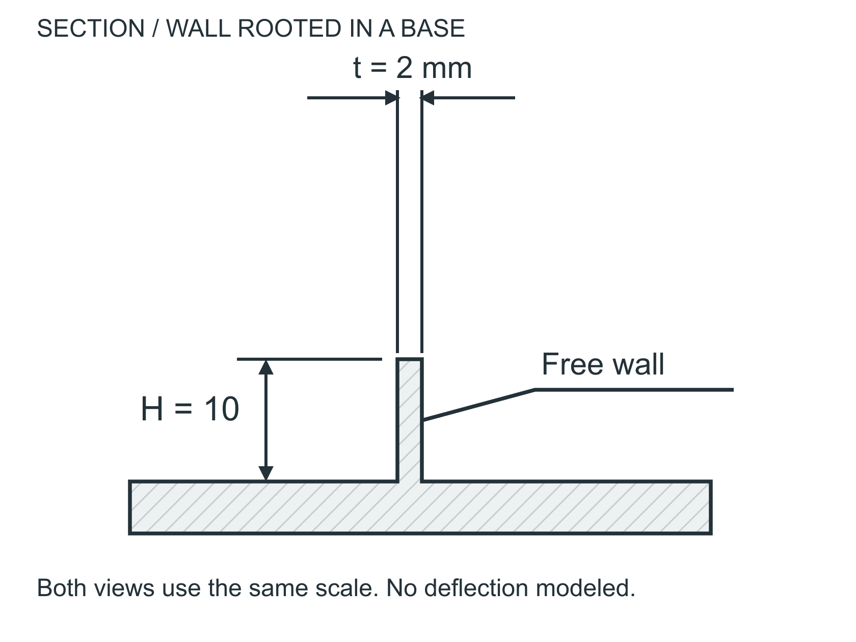
Below ~0.8 mm aluminum or ~1.0 mm steel, walls start chattering, deflecting, and fighting clamping forces. We can run thinner with sacrificial supports or special fixturing, but expect the cost to climb fast.
01
Thin walls, ribs & webs
- chatter
- deflection
- clamping forces
| Material | Recommended min wall | Absolute min (with support) | Notes |
|---|---|---|---|
| Aluminum 6061 | 0.8 mm (0.032″) | 0.5 mm (0.020″) | Sets the baseline — easiest to keep stable |
| Stainless 316L | 1.0 mm (0.040″) | 0.7 mm (0.028″) | Springs back; chatter risk on thin walls |
| Steel (4140 / 1018) | 1.0 mm (0.040″) | 0.7 mm (0.028″) | Stable, but watch heat-induced warp |
| Ti-6Al-4V | 1.5 mm (0.060″) | 1.0 mm (0.040″) | Heat distortion + chatter; conservative limits |
| Inconel 718 | 1.5 mm (0.060″) | 1.0 mm (0.040″) | Work-hardens fast on thin walls |
| Plastics (PEEK, Delrin) | 1.5 mm (0.060″) | 1.0 mm (0.040″) | Flex prevents deeper cuts; need gentle fixturing |
Wall aspect ratio matters too — a 0.8 mm wall that’s 50 mm tall is harder to hold than the same wall 5 mm tall. Above 8:1 height-to-thickness, expect sacrificial supports or fixturing surcharges.
02 · Holes & depth ratio
L:D drives drilling cost.
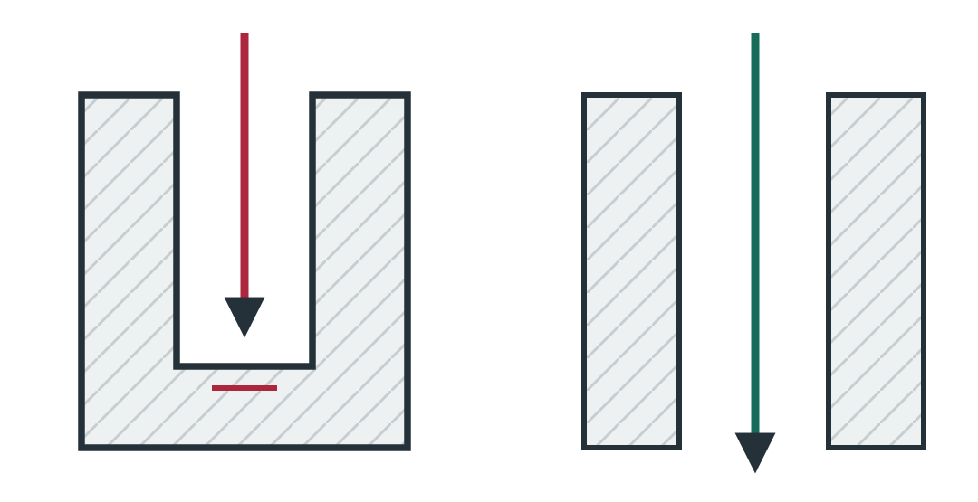
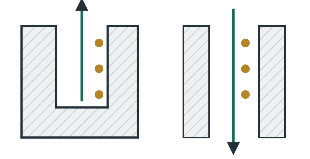
Hole depth-to-diameter (L:D) ratio determines what tooling is required. Up to about 3:1 is standard with a regular drill. Beyond that, peck cycles, coolant strategy, and tool selection all become factors. Past 10:1 you’re into gun-drilling territory — a real cost step.
The tradeoff: a 12:1 through-hole often costs far more than the same passage drilled from both faces as two 6:1 holes. We’re happy to flag opportunities like that during quote.
Relative cost — assumes conventional drilling on a CNC mill from one side. Wire EDM and rifle-drilling can be cheaper for very deep, very precise holes.
Up to 3:1
Standard drill bit. No special considerations. Cost roughly $0.50–$2 per hole in soft metals.
5:1 to 10:1
Peck cycle for chip clearance. Through-tool coolant helps significantly. ~1.5–2.5× cost.
10:1 and beyond
Gun drilling, BTA drilling, or EDM. Tooling and setup costs rise quickly. Talk to us before specifying.
03 · Internal corners
Tools have a radius. Plan around it.
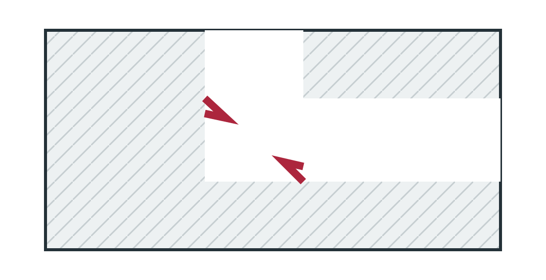
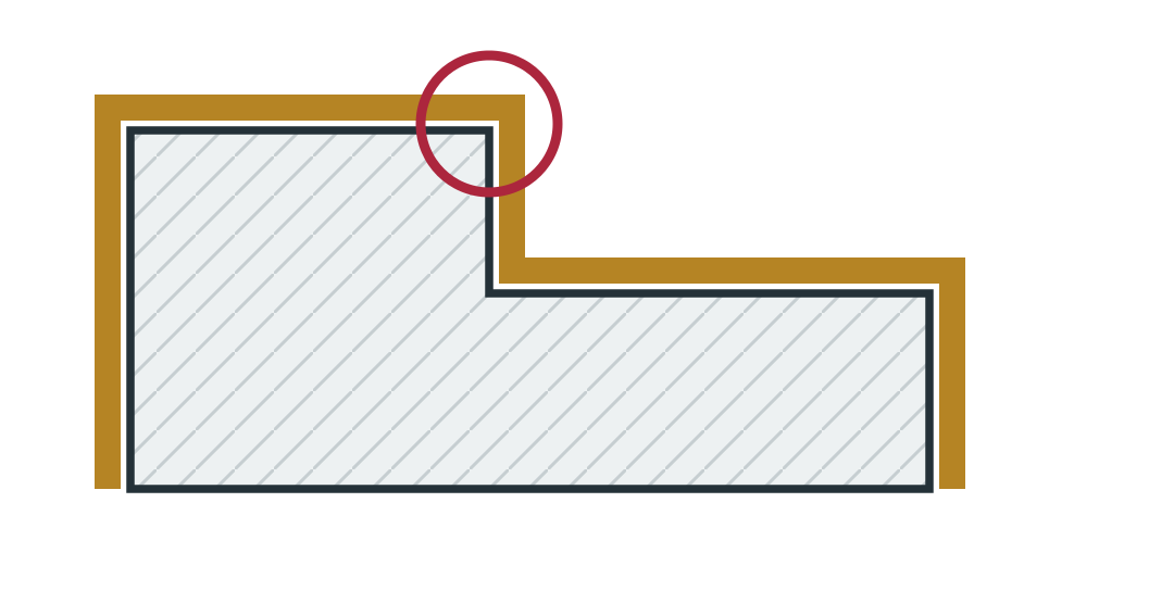
A square internal corner is impossible to mill — every endmill leaves a radius equal to its tool radius. Specifying a sharp internal corner forces an EDM follow-op or a tool diameter so small the floor takes forever to mill. Both are expensive.
Rule of thumb: internal corner radius ≥ 1.3× the radius of the tool that has to reach it — so a standard endmill can sweep the corner instead of dwelling. Size the radius up as the pocket gets deeper (it sets the smallest tool that can reach the floor). For most pockets, R ≥ 0.5 mm (0.020″) is essentially free; R ≥ 1.5 mm (0.060″) lets us use a stiffer, faster-cutting tool.
Pocket Corner Simulator
Adjust the slider values to simulate how pocket depth and internal corner radius dictate tool Reach Ratio ($L/D$), tool deflection, and feed rate penalties.
This pocket corner design accommodates a standard tool size and standard toolreach parameters.
04 · Threads
Tap, mill, or roll — pick deliberately.
For the same hole, threading method affects cost by 5×, strength by 30%, and reliability significantly. The general guidance:
Cut tap
Default for most production
Fast, cheap, well-understood. Works in any material. Risk: tap breakage in deep blind holes; chips need to clear.

Form (roll) tap
Strongest threads, no chips
Cold-forms threads from existing material. No chips. ~30% stronger than cut threads in ductile materials. Won’t work in cast iron or hardened materials.


Single-point / mill
When taps won’t fit or break
Larger threads (1″+), exotic materials, or where tap breakage risk is unacceptable. Slower but more controlled — recoverable on tool failure.
For threads in soft materials with frequent assembly/disassembly (aluminum brackets, plastics), strongly consider a steel thread insert (Helicoil, Keensert) — it costs less than re-machining the part after the third pull-out.
05 · Tolerances
Tighter tolerances cost more — exponentially.
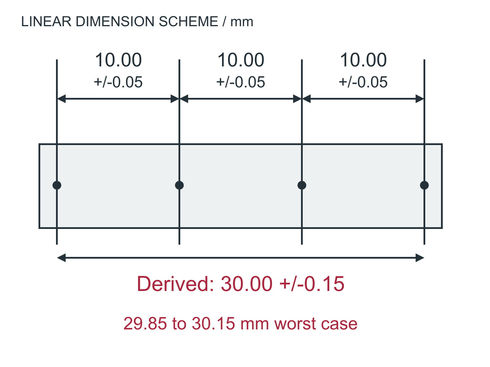
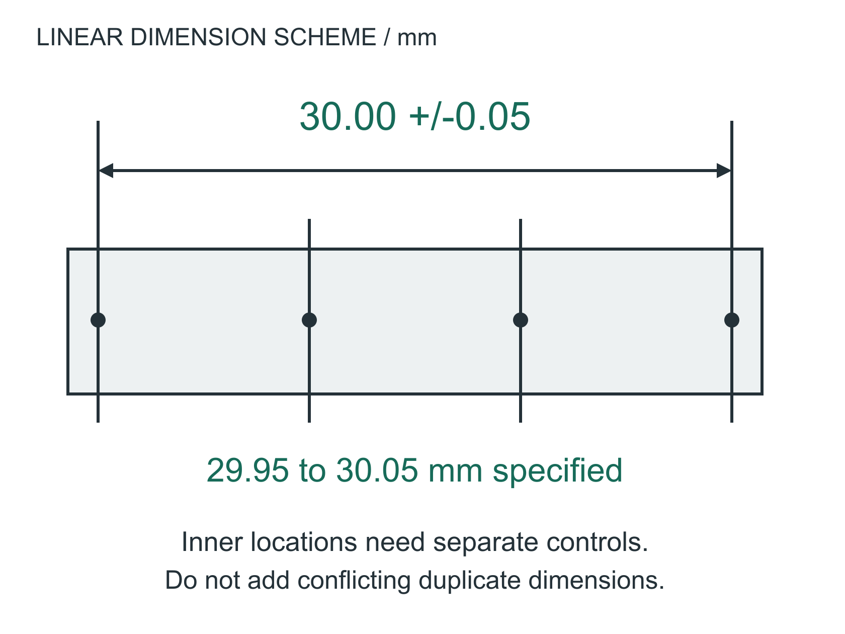
Doubling the tightness on a tolerance can double the cost of that feature. Tightening it 10× can multiply cost 5× or more. Specify the precision your application actually needs — not the CAD default.
Costs are typical relative multipliers per feature, holding all else equal. See our dedicated tolerances reference for achievable values per process.
For a deeper look — including ISO 2768 quick reference and a full tolerance-vs-process matrix — see the tolerances reference.
06 · Cost patterns
Patterns we look for during DFM review.
01
Tolerance grouping
Tightly toleranced features held in one setup are essentially free. The same tolerances spread across 4 setups stack up — and increase risk.
02
Datum scheme
Datums that align with how the part will be held in fixturing eliminate one or more setups. The 'right' datum scheme often cuts 20% off cost.
03
Surface finish callouts
Drawings often default to 32 µin everywhere — which doubles finishing cost. Spec a fine finish only where the function needs it.
04
Symmetry
Mirror or reflective symmetry lets us fixture once and machine both halves. Asymmetric variants for cosmetic reasons add real cost.
05
Standard sizes
Drill sizes are cheap; reamed and ground sizes are expensive. Same for thread sizes — UNC/UNF before metric specials.
06
Material swap
Spec'd 17-4PH H900 because the legacy drawing did, but the part doesn't see >150 °C? Could be 4140 or 6061. Material is half the cost.
Keep exploring
Related tools & references
Score your drawing against 32 manufacturability checks.
How tolerance class maps to machining cost.
Use GD&T instead of stacked ± tolerances where it adds clarity.
Standard title block, notes, and default tolerances.
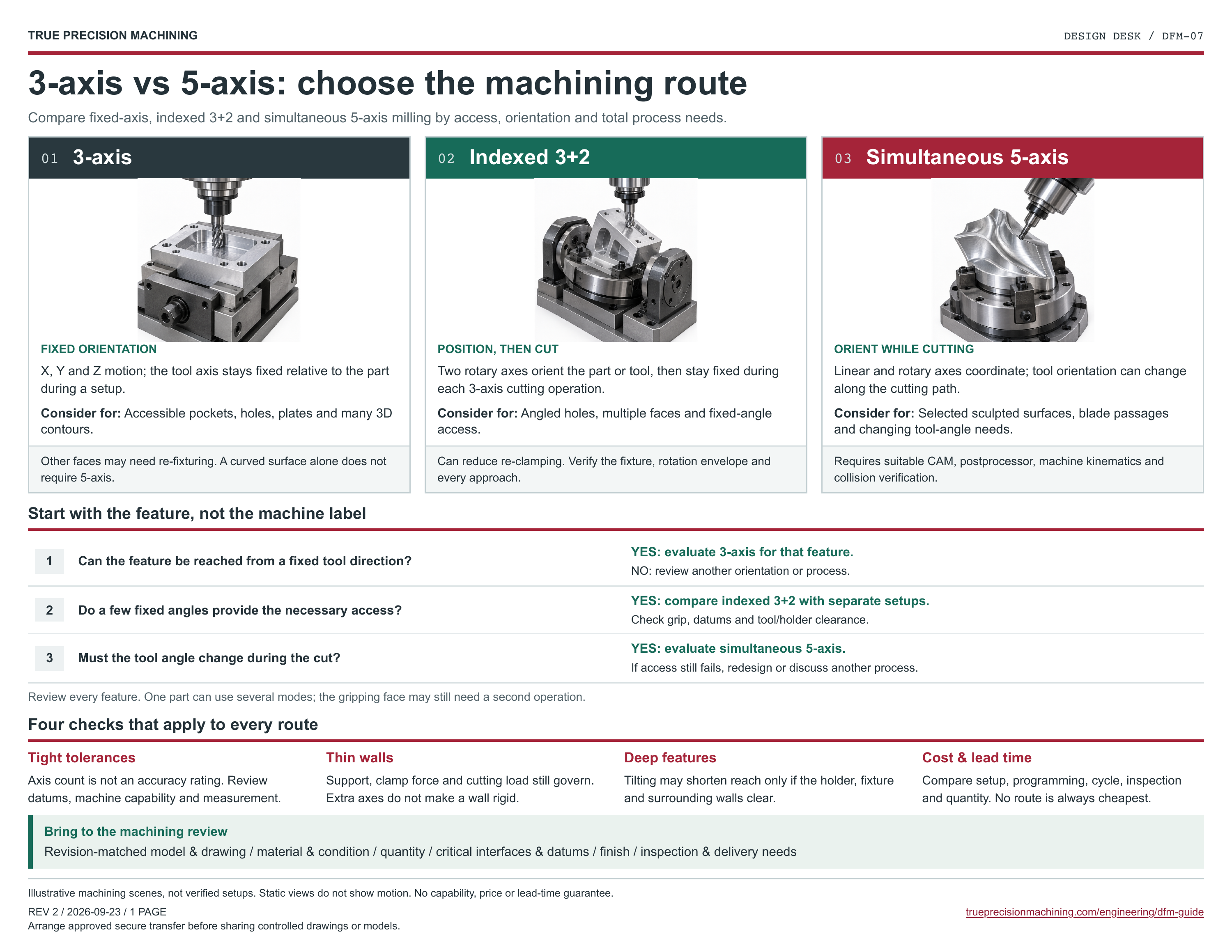
Design geometry so it routes to the fewest setups.
See where design choices land in the final part price.
Technically reviewed by the True Precision Machining engineering team · Last reviewed June 2026
Standards referenced: ASME Y14.5-2018, ISO 2768
Send us a drawing for DFM review.
Free, no obligation, usually back to you within one business day. Send a STEP file — we'll flag manufacturability concerns and quantify cost-reduction options before quoting.
Quotes in 24 hours