



Engineering · GD&T
Flatness.
A 3D form tolerance that controls how flat a planar surface must be. All points on the surface must lie within a tolerance zone bounded by two parallel planes separated by the tolerance value. No datum required — flatness is the surface vs itself.
01 · Definition
Two parallel planes.
Flatness creates a tolerance zone bounded by two parallel planes separated by the tolerance value. The entire toleranced surface must fit between those planes. The planes float in space — they don’t reference any datum or external feature. They simply have to fit somewhere around the surface.
For machined surfaces, flatness is independent of orientation. A perfectly flat surface that’s slightly tilted relative to the rest of the part still meets a flatness callout — though it might fail a parallelism callout. That’s the key distinction: flatness is about the surface itself; parallelism brings in a datum reference.
02 · FCF and example
0.001 flatness on a mounting face.
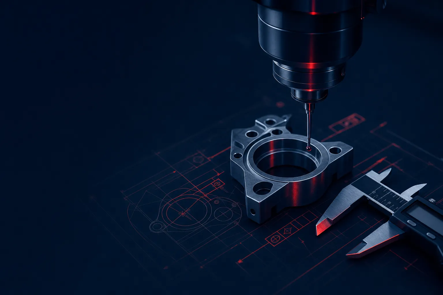
A 6″ × 4″ mounting face with a ⏥ 0.001 callout. The entire surface must fit within two parallel planes 0.001″ apart. Inspection: granite plate with a height gauge (surface leveled on jack screws first), or CMM scan of the surface with profile-best-fit analysis.
For 0.001″ or tighter flatness over a substantial surface, you need stress-relieved material (MIC-6 cast plate is the standard) and precision-class machine equipment. Standard 6061-T6 wrought plate releases internal stress over time and won’t hold tight flatness for long-term applications. See cast vs wrought plate comparison.
03 · Inspection
Best-fit zone calculation.
Flatness inspection on a CMM uses the “minimum zone” method: software fits two parallel planes around the measured points, oriented to give the smallest separation. That separation is the actual flatness. ASME Y14.5 specifies this method; older drawings sometimes call out “least squares” flatness, which gives a different (slightly larger) result.
Granite-plate inspection with a height gauge is faster but less precise. Set the part on three jack screws and level the toleranced surface first; if the part simply rests on its opposite face, the sweep measures parallelism to that face, not flatness. Then take readings at a grid of points, find the highest and lowest, and the difference is approximate flatness. Adequate for 0.005″-class work; not for 0.001″.
We use a 2025 Hexagon Global S 7-10-7 CMM with scanning probe for tight flatness verification — see CMM deep-dive.
Related
- Straightness — 2D version, line elements
- Parallelism — flatness referenced to a datum
- Full GD&T symbols reference
Keep exploring
Related tools & references
Full feature-control-frame symbol reference.
The 2D line-element form control flatness extends to a whole surface.
Flatness of a face held parallel to a datum.
Check how flatness and other form tolerances accumulate.
How tight to call out flatness — and what it costs to hold.
Technically reviewed by the True Precision Machining engineering team · Last reviewed June 2026
Standards referenced: ASME Y14.5-2018
Have a part that needs to be made right?
Tell us about your part and we'll quote within 24 hours. Aerospace, medical, and defense work welcome.
Quotes in 24 hours