
Engineering · Reference
Welding symbols — AWS A2.4 reference.
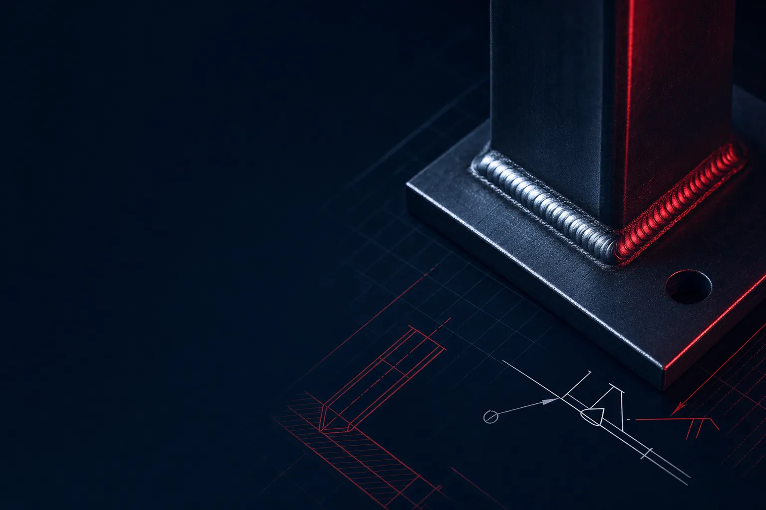
How to read a welding symbol per AWS A2.4: the reference line, the arrow and what arrow-side vs. other-side means, and the tail that carries the process and spec. Includes the full set of weld-type symbols (fillet, square-, V-, bevel-, U-, J-groove, flare welds, plug/slot), supplementary symbols (weld-all-around, field weld, melt-through, backing, contour), and what every dimension on the symbol means.
Interactive Breakdown
Anatomy of an AWS A2.4 welding symbol
Tap a labeled region of the symbol to see what it controls.
The horizontal backbone of every weld symbol.
In this AWS A2.4 example, weld symbols BELOW the reference line apply to the arrow side; symbols ABOVE apply to the other side. ISO 2553 system B also uses a single reference line; system A uses continuous and dashed lines. Confirm the system specified on the drawing.
Weld-type symbols
The basic weld symbol identifies the joint geometry. Each is drawn touching the reference line; groove symbols carry depth, angle, and root dimensions (see below).
| Symbol | Weld type | Definition | Typical use |
|---|---|---|---|
| Fillet | Triangular cross-section weld deposited in the corner of two surfaces that meet at roughly a right angle. The right-triangle symbol sits on the reference line; the vertical leg is drawn on the left. | Lap, tee, and corner joints — the most common weld in fabrication. No edge preparation required. | |
| Square-groove | Two square (un-prepared) edges butted together with a small root opening. Shown as two parallel vertical lines on the reference line. | Thin butt joints (typically up to ~3/16 in / 5 mm) where no bevel is needed for penetration. | |
| V-groove | Both members beveled symmetrically to form a V opening (standard 60° included angle). Groove depth and angle are dimensioned on the symbol. | Full-penetration butt joints on medium-to-thick plate where both sides can be prepared. | |
| Bevel-groove | Only one member is beveled; the other stays square. Per A2.4 the perpendicular leg of the symbol is always drawn on the left, whatever the joint orientation; the arrow line is broken (kinked) toward the member to be prepared. The break may be omitted when it is obvious which member is prepared. | Tee and corner joints, or butt joints where only one side can be accessed/prepared. | |
| U-groove | Both members prepared with a radiused (U-shaped) groove and a vertical land. Uses less filler than a V on heavy sections. | Thick plate (~3/4 in+ / 19 mm+) full-penetration butt joints where weld-metal economy matters. | |
| J-groove | One member prepared with a J (radiused) groove, the other square — the single-sided counterpart to the U-groove. | Heavy tee and corner joints needing controlled penetration with reduced filler vs. a single-bevel. | |
| Flare-V-groove | Groove formed by the natural radii of two curved members (e.g. two round bars or the corners of two tubes) meeting to form a V-like cavity. | Joining round/tubular members or rolled edges where the curvature itself forms the groove. | |
| Flare-bevel-groove | A curved member (round bar or tube corner radius) welded to a flat, square member — the curvature of one part forms the groove. | HSS-to-plate and round-bar-to-plate joints common in tube and structural fabrication. | |
| Plug / Slot | Weld that fills a round hole (plug) or elongated slot in the top member of a lap joint, fusing it to the member beneath. Size (hole diameter or slot width) is shown to the left of the symbol. | Stitching overlapping plates together where access for an edge weld is limited. |
Supplementary symbols
These attach to the weld symbol to add extent, location, finish, or root conditions.
| Symbol | Name | Meaning |
|---|---|---|
| Weld-all-around | Open circle at the junction of the arrow and reference line: the weld is continued completely around the joint perimeter. | |
| Field weld | Solid flag (pennant) at the arrow/reference-line junction: the weld is to be made in the field (on site), not in the shop. | |
| Melt-through | Filled semicircle on the side opposite the weld symbol: 100% joint penetration with visible root reinforcement is required from a single-side weld. | |
| Backing / spacer | Rectangle on the side opposite the weld symbol (shown): a backing bar is used at the root of the joint. A spacer is drawn differently — a rectangle straddling (centered on) the reference line, between the arrow-side and other-side groove symbols. | |
| Contour — flush | Straight line across the face of the weld symbol: the finished weld face is to be flush (flat). A finish letter (G, M, C, etc.) may follow. | |
| Contour — convex | Outward arc over the weld symbol: the finished weld face must be convex (bulged outward). | |
| Contour — concave | Inward arc over the weld symbol: the finished weld face must be concave (dished). Reduces effective throat on a fillet. |
A letter placed with a contour symbol specifies how the weld face is finished:
Reading the numbers
What the dimensions on a weld symbol mean.
Numbers and notes have fixed positions around the weld symbol. Get the position right and the value is unambiguous.
- Fillet leg size — to the LEFT of the symbol.
A single value (e.g. ¼) gives the leg length of an equal-leg fillet. Unequal legs are written as two values separated by a multiplication sign (e.g. 3/8 × 1/4), with a note clarifying orientation.
- Groove depth and groove angle.
Depth of bevel/preparation is shown to the LEFT of the symbol; the effective throat (if different) follows in parentheses. The included groove angle is placed outside the symbol (e.g. 60°), and the root opening is shown inside the symbol.
- Length and pitch — to the RIGHT of the symbol.
For an intermittent fillet, two values separated by a hyphen give length–pitch: 2-4 means 2-inch weld segments on 4-inch centers (center-to-center). Omitting the length means the weld runs the full joint.
- Plug / slot size.
Hole diameter (plug) or slot width is shown to the LEFT of the symbol; depth of fill, angle of countersink, and pitch are placed in their respective positions.
- The tail carries process and spec.
The V-shaped tail at the far end of the reference line holds the welding process (SMAW, GMAW, GTAW, FCAW, SAW), filler/electrode classification, applicable specification or WPS, and notes like preheat or PWHT. No tail = no specific process called out.
Standards & cautions
AWS A2.4 vs. ISO 2553 — and common pitfalls.
- ISO 2553 offers systems A and B.
AWS A2.4 uses below for the arrow side and above for the other side. ISO 2553 system A uses continuous and dashed reference lines; system B uses a single reference line with below/above placement. A single line alone does not identify the governing standard.
- Arrow side is below the line — a frequent misread.
In AWS A2.4 the symbol below the reference line is the arrow side. It trips up readers who expect "arrow points up, so symbol up." Both sides can carry a symbol for a two-sided (e.g. double-V) weld.
- The broken arrow is intentional.
For bevel- and J-groove welds, a kinked (broken) arrow line points to the specific member that must be prepared. It is not a drawing error. A2.4 allows the break to be omitted when it is obvious which member is prepared.
- Symbol ≠ cross-section.
The weld symbol is a schematic, not a scaled cross-section. The actual geometry, sizes, and tolerances come from the dimensions and the governing weld procedure — read both.
- For the mating machined parts, control geometry with GD&T.
Weld symbols define the joint; the machined features they connect are toleranced with GD&T symbols. See also the engineering standards index and the ASTM / MIL-spec library for the documents a drawing may invoke.
Related references
Keep reading.
All 14 geometric tolerance characteristics per ASME Y14.5, with definitions and datum rules.
The standards a drawing commonly invokes — dimensioning, materials, finishes, and inspection.
Quick lookups for the ASTM and MIL specifications referenced on aerospace and defense prints.
Aerospace Material Specifications by alloy and process, with what each one governs.
UN/UNF and metric thread dimensions, classes of fit, and tap-drill sizing.
Target torque from preload, diameter, and friction — for the fasteners that join a weldment.
From the shop
Need the machined mating parts for a weldment?
True Precision is a CNC machining shop. If your assembly calls for welding, we machine the components to print and can coordinate the welding step with a qualified partner so the finished, machined assembly meets your tolerances. Send the drawing and we’ll quote the machined scope.
Keep exploring
Related tools & references
The other half of feature-control callouts on a drawing.
A clean title block and annotation layout to start from.
Ra grades and drawing symbols for machined faces.
How to call out dimensional tolerances alongside joint notes.
Controls form and location of complex machined surfaces.
Technically reviewed by the True Precision Machining engineering team · Last reviewed June 2026
Standards referenced: AWS A2.4, ISO 2553, ASME Y14.5-2018
Have a part that needs to be made right?
Tell us about your part and we'll quote within 24 hours. Aerospace, medical, and defense work welcome.
Quotes in 24 hours